
[BME] Instrumentation amplifier
Instrumentation amplifier
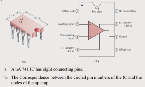
1. The Operation Amplifier (op amp)
연산 증폭기
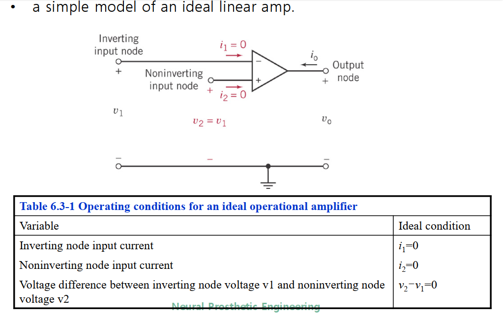
Ideal operational amplifier
하나가 아닌 두 개의 input를 갖는다.
- inverting input
-
noninverting input
ideal한 상황은 input으로 들어가는 current가 없고 두 개의 노드에 걸리는 voltage의 차이가 없는 것이다.1) Infinite
A_v
2) Infinite input impedance
3) Zero output impedance
Open loop의 OP amp는 gain이 워낙 크기 때문에 input difference가 조금이라도 발생하면 한쪽으로 크게 치우친 output이 출력되기 때문에 사용할 수 없다.
따라서 OP amp는 반드시 negative feedback을 사용하여야 한다.
OP amp circuit
이 회로를 분석하기 위해서는 $$ V_1 = V_2 $$ 의 조건을 이용해야한다. (virtual ground)
virtual ground : op amp의 두 input은 zero
2. Inverting amplifier
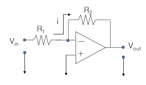
R_2 를 통해 negative feedback을 걸어주고 (+) input를 ground에 연결한다. V_{in}과 V_{out} 의 관계를 구해야 한다. (-) input에는 current가 없으므로 모든 전류를 R_2로 흐른다.
i = \frac{V_{in}}{R_1}
V_{out} = i \cdot R_2 = V_i (-\frac{R2}{R_1} )
Gain = \frac{V_o}{V_i} = -\frac{R_2}{R_1}
3. Unity buffer (voltage follower)
Gain이 1인 회로이다. 즉, 회로를 통한 voltage의 변화가 없다. 하지만 이 회로가 유용한 이유는 op amp의 훌륭한 impedance status를 이용할 수 있기 때문이다.
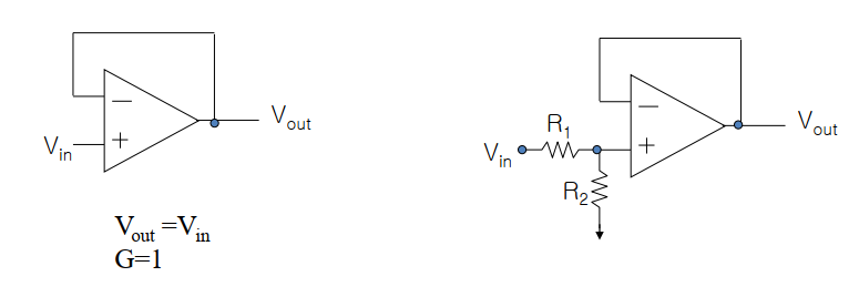
4. Noninverting amplifier
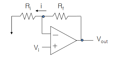
V_o = i \cdot (R_i + R_f)
V_i = i \cdot R_i
A_v = \frac{R_i + R_f} {R_i}
5. Common Mode Rejection Ratio (CMRR)
CMRR은 differential mode gain을 common mode gain으로 나눈 값으로 dB로 표현한다. 이 값은 크면 클수록 좋다.
우리나라 대부분의 건물에는 60Hz의 power line이 존재한다. 즉, 모든 회로는 이 power line의 영향을 받게 되는데 절대적으로 크기가 작은 생체의 전기신호를 detect하기 위해서는 외부 노이즈를 최대한 작게 하는 것이 좋다. 다시 말해 common mode gain은 작게 하고 differential mode gain을 크게 하는 것이 이상적이다.
6. Instrumentation Amp
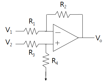
Differential mode
V^{+} = V_2 \cdot \frac{R_4}{R_3 + R_4}
V^{-} = (V_0 - V_1) \frac{R_1}{R_1+R_2} + V_1
From ~ V^{+} = V^{-}
V_0 = \frac{R_4} {R_3 + R_4} (1+\frac{R_2}{R_1})V_2 - \frac{R_2}{R_1} V_1
if ~ \frac{R_3}{R_4} = \frac{R_1}{R_2} ~ \rightarrow ~ V_0 = \frac{R_2}{R_1} (V_2 - V_1), ~ G_d = \frac{R_2}{R_1}
Common mode
V_1 = V_2 ~ \rightarrow ~ V_0 = 0 ~ \rightarrow ~ G_c = 0
CMRR = \frac{G_d}{G_c}
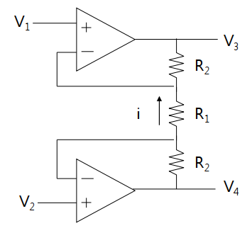
7. For high input impedance
위 회로를 이용하면 앞단에 달린 저항들 때문에 Op amp의 훌륭한 impedance status를 사용할 수 없다. 따라서 위 회로 앞에 다음과 같은 회로를 연결해 준다.
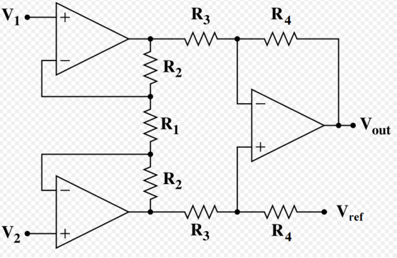
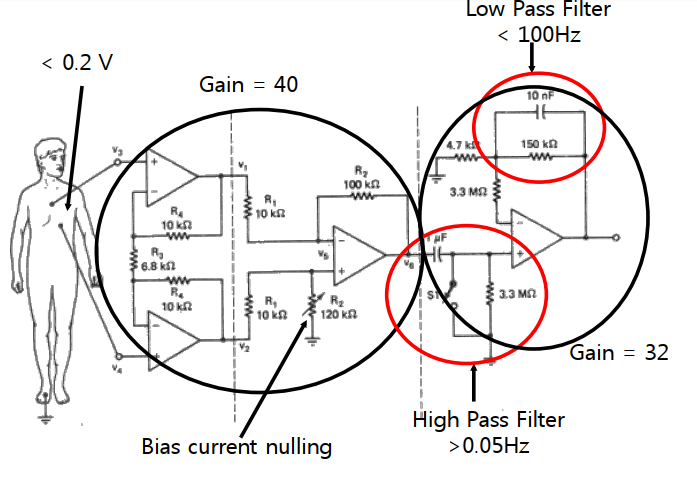
8. Complete design of instrumentation amp
Filters
Low pass : 저주파 신호를 통과시킨다.
High pass : 고주파 신호를 통과시킨다.
Band pass : 중간값 신호를 통과시킨다.
Notch : 어느 한 frequency만 지정해서 뽑아낸다.
1. Types of filters
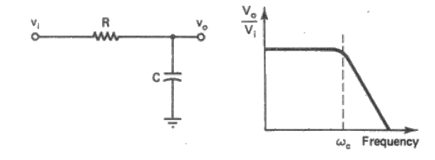
Passive first-order low pass filter
high fq. 신호들을 제거하는 역할을 한다. (적분의 형태)
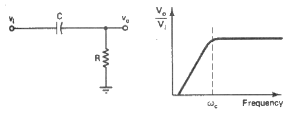
Passive first-order high pass filter
Passive second-order low pass filter
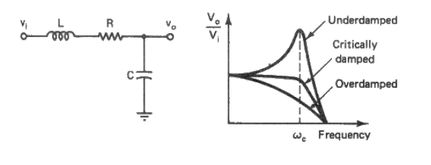
- order를 높이면 높일수록 경계값의 slope가 abrupt해진다.
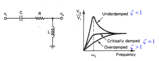
Passive second-order high pass filter
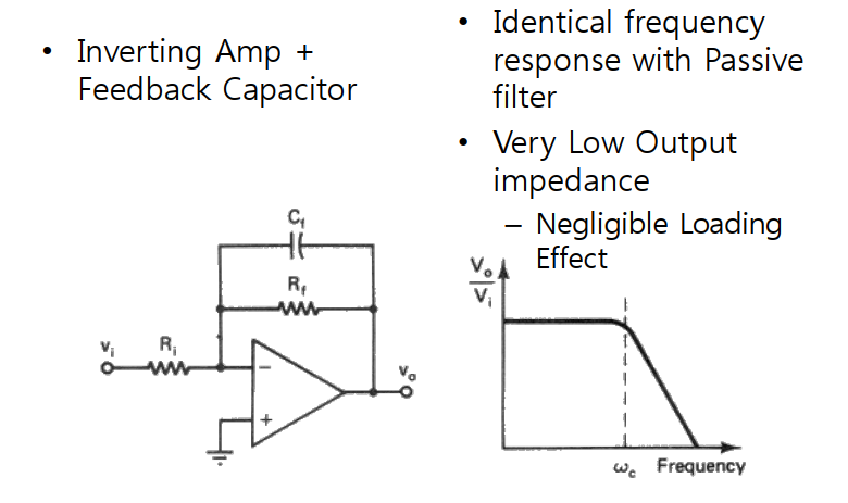
Active first-order low pass filter
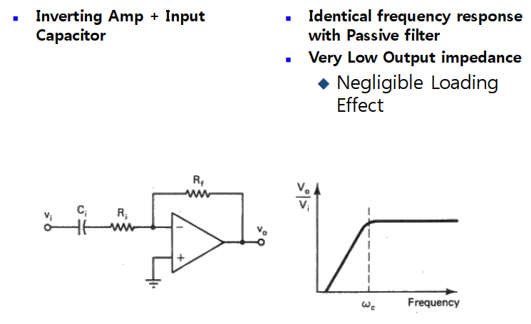
Active first-order high pass filter
Example: ECG amplifier
2. Interference and safety
- Noise : random
- Interference : Not random, comes from a known source
Dominant interference : 60 Hz
through
- AC capacitive coupling
- AC inductive coupling
- Ground loops
solution
- Elimination at the source
- use of instrumentation amps
- star ground(one true ground, 전위차를 없애기 위함)
- Filtering